Hello,
In this post I give an overview of my dissertation that I completed at University which was my first attempt at working on something CFD related. Like most things that you tend to review in hindsight there is an element of cringe that kicks in, but we all need to start somewhere and no one is perfect from the offset (I love and hate hindsight).
Anyway, growing up I have always been facinated with the automotive & motorsport industry and particularly intruiged by the aerodynamic designs of Formula 1 vehicles especially the 2007/2008 designs when I was 11-12 years old.
When it was time for me to select my dissertation project, I was keen to work on something related to aerodynamics/CFD. As a member of the university Formula Student team I had an oppurtunity to use the vehicle as a base for proposing an aerodyanmics project. What I proposed, focussed on simulating wings for the vehicle as introductory research that the team could then further develop from. It was important for the project to keep it simple and not to place the cart infront of the horse so to speak.
The project was titled 'Research and Development of Aerodynamics for a Formula Student Race Car'
Research
Like all tasks in life a degree of understanding needs to be considered before tackling the problem. Initial reserch was conducted to understand the fundmentals of fluid flow around an aerofoil as well as the physics solvers for the simualtions and Formula student design rules etc.
The momentuum equaton that I decided to use for this project was Spalart-Allmaras. Spalart-Allmaras or S-A is a one equation model RANS equation, typically used in CFD for modelling aerodynamics. The advantages of using S-A is its ability to calculate attached wall bounded flows and flows with mild separation which is perfect for wing geometries.
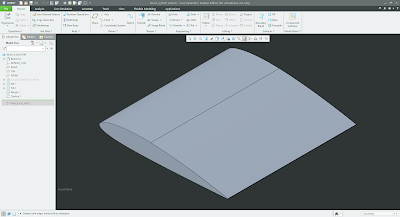
When looking at the rules I created two volume boxes that were used as the maximum modelling region which can be seen in the image below.
The software
Star CCM+ was used for the project as it is the software that the University has licenses for. I found the software very nice to use over the course of the project even if it did take some getting use to. I feel like I'm in the same situation now with OpenFoam staring blankly into text files as opposed to a slick looking user interface like with Star CCM.
Simulations
Meshing
The meshing used a combination of polyhedral and prism layers to capture the geometry. Polyhedral cells were used to capture the free stream velocity and have an advantage of calculating complex swirling flows, whereas the prism layers were to captures the boundary layers which can be seen in the image below. The prism layers have a non-linear cell growth just like the velocity that also has a non linear rate of change.
Validation case
From watching motorsport you often tend to hear about correlation issues. This is something that can happen easily within CFD as splitting a domain into millions of tiny cells never 100% perfectly captures the geometry and enviroment especially with sub-optimal mesh settings.
To overcome this I ran a validation case against the NACA 0012 aerofoil. This is a common symmetrical design which produces negligable lift at 0° but at an angle of 10° it has a lift coefficiant of 1.08-1.09. With this knowldege I could refine the mesh and run a grid convergence study which would show the least amount of cells required to achieve a realistic result within a 10% window of error.
The design
The plan for developing the rear wing was simple. Start by using a single aerofoil and plot the lift and drag at different angles. From there I could add a second aerofoil (flap) and see how the size of the slot gap effects the the lift and drag of the system. I would then find the optimal angle of the flap element and add a gurney flap to see how that effects the system. Lastly I would add endplates and simualte the wing in 3D.
In the case of a front wing you would need to add in a step where you see how the height difference from the ground effects the lift and drag results of the simualtion.
From my research I found two aerofoils that produced a high lift/drag ratio, these being s1210 and s1223 aerofoils that are primarly used on heavy lift aircraft. Data from the simulations could be plotted on the graphs below which show the lift vs AoA and the lift/drag vs AoA.
the simualtions show that the s1223 produces more lift which was to be expected before conducitng the simulations. In this case it has a stall angle of 14° but as there was a flap being added the lift/drag was more important. The most efficient angle for the s1223 was at 3°.
With a flap element being addded research has shown that the optimum size is 25%-30% of the main plane chord. In this case I used 30% as I wanted to maximise the surface area due to the vehicle operating at low velocity. having a slot gap of 2% compared to the overall chord length proved to be the most efficient gap.
With this in mind I could then begin changing the angle of the flap. I ran simulations with 2° increments from 30° until the stall point. With this I found that having the flap at 40° produced the maximum amount of lift to 3.128.
The advantage of crating a multi element wing is that you can take some of the high pressure gradient flow from the top surface of the main plane and use it to keep the flow attached to the low surface side of the flap and increases lift as you can run the flap at a more aggresive angle.
To further increase the peformance of the geometry I added a gurnery flap to the trailing edge of the flap wing. I incorporated a guerny flap of 1% in relation to the chord length and this was able to increase the lift by 5%.
A clear effect from adding the gurney flap is seeing an increase in size of the high pressure region (I should have edited the scalar bar to be set over the same pressure size).
With the general geometry of the aerofoils finalised I could begin adding endplates and run the simulations in 3D. With the simulations running in 3D there are more cells and thus becomes more computationally expensive. A way to minimise the time loss was to simulate half of the geometry and mirror the results along the centreline.
Two designs were created, one with 50 mm offset around the aerofoil geometry and the second extends a further 350mm to fill the available volume below the aerfoil.

From running the simulations, the results showed that having a larger sized endplate increases the lift coefficient of the design. The importance of having endplates is that it reduces the high pressure air from spilling over into the low pressure region on the lower surface which causes the generation of vortices which then reduces pressure at the edge of the wing resulting in a loss of lift and an increase in drag.
Obvoiusly there will be loses from the due to the objects infront blocking the wing for example, driver, air intake, roll hoop etc. I tried running a full simualtion of the car wing with the design however I was having issues the bodywork geometry and decided to simplify the system and only run critical components that were blocking the rear wing. It wasn't ideal but still gave some interesting results to analyse.
Visually looking at the design below (front view) you can clearly see that towards the centre of the wing the pressure on to the top surfaces reduces and the pressure on the lower side increases.
Rendering the streamlines from the objects in front there is a vortex that is genertating from where the drivers helmet & headrest would be positioned.
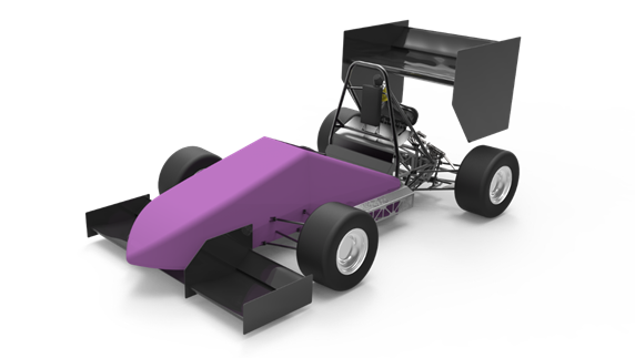
Completed design
The completed design as shown below is a mock up of how the car could look with the designed aero package. It can produce 18.5% of it's total weight in downforce at 56kph (35mph) which although doesn't seem like alot, it is a resonable amount consiering it's travelling at such a low velocity and the design is fairly rudimentary. The design cold also lap 0.242s faster around the 16.75m diamter skidpad.
Learning outcomes
Of course there were bases that wasn't touched in this project, like how the design is effected by various dynamic motions of the vehicle as it would most likely be a sprung mounted system or looking into the cost and weight that the design adds as Formula Student competition is more than just creating a design and bolting onto the car, it needs to be justified against mainy measurables.
However it gave me a good insight into runnnig fluid mechanic problems and improved my understanding of the fundamentals involved.
I do think the project lacked mesaurable targets initially and the initial goals of the project was quite vague.
For example I could've started with calculating a skid pad time from looking at what other vehicles could acheive with a similar aerodynamic package and from there I could generate a coefficient lift target for the wings to achieve.


Comments
Post a Comment