Posts

Modelling NACA 4 digit aerofoil from equations (in creo)

Image
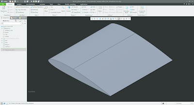
Hello, This post will cover the conception stage of aerofoil profiles and how to improve the CAD workflow for large scale simulations where multiple geometries need to be created and assessed. One thing I have noticed is that aerofoil CAD geometry is typically produced from generating a curve through points. I have always found this cumbersome as you have to go online (typically airfoiltools.com) find the aerfoil shape that you want, download the .csv file and import it into your CAD package (with Creo you have to import .pts which requires further work and the points need to be put into a notepad file). However, aerofoil geometries are construcuted from equations, so why not create a curve from an equation? You can set the control paramters of the design and be free to manipulate the geometry which will save you from going online to find the various profiles that you want to test. The Equations The NACA 4 digit profile is goverend by three distinct parameters (thickness, maximum cambe

OpenFoam: Flate plate

Image
 Hello, This post will detail the process of running a flate plate simualtion within OpenFoam. As I'm a newbie when it comes to OpenFoam I thought the best place to start would be running a simple simulation to understand the pre-processing which is my main goal for this simulation. Flate Plate A flat plate is as it says in the name, you have a plate that is flat and the fluid will pass over it at the specified inlet velocity condition. The importance of running this type of simulation is to model the no-slip effect of the wall. No slip occurs because of the friction caused by the particles interacting with the surface. The further from the surface the velocity increases until it reaches the free stream velocity. Accuratly modelling the boundary layer will provide accurate predictions of wall shear stress which in turn leads to improved predicitons for surface pressure, pressure gradient and forces such as lift and drag (aerofoil). The image below displays fluid passing along a wal

My first project

Image
Hello, In this post I give an overview of my dissertation that I completed at University which was my first attempt at working on something CFD related. Like most things that you tend to review in hindsight there is an element of cringe that kicks in, but we all need to start somewhere and no one is perfect from the offset (I love and hate hindsight). Anyway, growing up I have always been facinated with the automotive & motorsport industry and particularly intruiged by the aerodynamic designs of Formula 1 vehicles especially the 2007/2008 designs when I was 11-12 years old. When it was time for me to select my dissertation project, I was keen to work on something related to aerodynamics/CFD. As a member of the university Formula Student team I had an oppurtunity to use the vehicle as a base for proposing an aerodyanmics project. What I proposed, focussed on simulating wings for the vehicle as introductory research that the team could then further develop from. It was important for